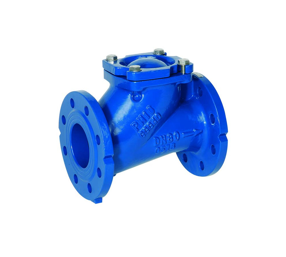
A check valve is a critical component in piping and instrumentation diagrams P&IDs, designed to allow fluid to flow in one direction while preventing reverse flow. It is often used in systems where backflow could lead to damage, contamination, or inefficiency. In P&IDs, check valves are typically identified by specific symbols and annotations that provide essential information regarding their type, function, and installation. The most common symbol for a check valve in a P&ID is a circle with a diagonal line passing through it, sometimes accompanied by a spring or an arrow indicating the flow direction. The arrow signifies the direction in which the fluid is permitted to flow, helping engineers and operators understand how the valve operates within the system. The use of standardized symbols ensures clarity and consistency in understanding the function of check valves across different projects and industries.

There are various types of check valve symbol, each with its own distinctive features, such as swing check valves, ball check valves, and lift check valves. These types are often identified in P&IDs by specific suffixes or additional notations. For example, a swing check valve may be represented with a SW or SC suffix, while a ball check valve might have a BC identifier. Each type of valve serves a different purpose and is selected based on factors like pressure, temperature, flow rate, and the potential for contamination. Check valves in P&IDs are also accompanied by relevant technical information, such as the valve’s size, material, pressure rating, and other specifications. This information is crucial for engineers to ensure that the valve will perform optimally within the system and meet the required standards for safety, durability, and functionality. The size and pressure rating of the valve are typically specified alongside the symbol, and may be annotated as a number or fraction to indicate the appropriate dimensions and pressure class.
Additionally, check valves in P&IDs may be associated with other components, such as pumps, filters, or pressure relief valves, which provide context for their operation within the system. For instance, a check valve placed downstream of a pump prevents backflow that could damage the pump or other sensitive equipment. When reviewing P&IDs, engineers must carefully examine these connections to ensure that check valves are correctly placed to prevent reverse flow and maintain the integrity of the entire system. In summary, check valve identification in p&id symbols is vital for engineers to design, troubleshoot, and maintain piping systems efficiently. By understanding the symbols, notations, and types of check valves, engineers can ensure that these components perform their intended functions effectively, thereby preventing system malfunctions and improving overall system reliability. Proper identification and understanding of check valves in P&IDs contribute significantly to the success of engineering projects in industries such as oil and gas, water treatment, and chemical processing.