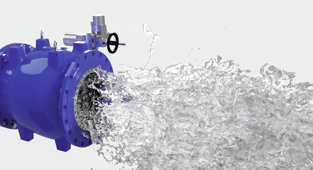
The check valve symbol is a fundamental part of Piping and Instrumentation Diagrams P&IDs in engineering. P&IDs are schematic diagrams that represent the layout, control, and operation of piping and instrumentation systems in industrial facilities, such as refineries, chemical plants, and power generation plants. These diagrams play a crucial role in ensuring that processes operate efficiently, safely, and as intended. A check valve is a type of valve that allows fluid liquid or gas to flow through it in only one direction, preventing backflow. In a process system, backflow can cause contamination, compromise product quality, damage equipment, or even pose safety risks to personnel. The check valve ensures that such undesirable reverse flow is prevented, safeguarding the system and maintaining process integrity. In most P&IDs, the check valve symbol is represented as a simple, recognizable icon, typically comprising a triangle pointing in the direction of permitted flow, sometimes with a line blocking the opposite direction, emphasizing its one-way nature.

This straightforward symbol effectively communicates the function of the check valve within the system, aiding engineers and technicians in understanding the flow paths and control mechanisms in place. While the basic check valve symbol is straightforward, variations may exist depending on the type of check valve being used or the specific industry standards applied. Common types of check valves include swing check valves, lift check valves, and ball check valves, each with unique characteristics suited to different applications. Swing check valves, for instance, are often used in large pipelines where minimal pressure drop is required, while lift check valves are more suitable for applications involving higher pressures. Each type might have a slightly different representation on a P&ID, indicating its specific design and function within the process system. Understanding the check valve symbol on P&IDs is critical for both the design and operation of process systems. Engineers need to consider factors such as fluid properties, flow rate, and system pressure to select the appropriate type of check valve for each application.
The symbol’s presence on a P&ID informs operators and maintenance staff about flow control points, enabling them to monitor and maintain the system more effectively. For instance, if a maintenance issue arises involving unexpected backflow, operators can refer to the P&ID to locate and inspect the check valve, ensuring it is functioning correctly and preventing costly downtime or repairs. Additionally, the check valve symbol on a P&ID enhances communication between various stakeholders involved in the lifecycle of a process facility. Designers, contractors, operators, and maintenance teams all rely on accurate P&IDs to understand the system layout, making it essential for these diagrams to be standardized and clearly annotated. In this way, the check valve symbol, like many other symbols on a P&ID, serves as a universal language, allowing professionals to interpret and manage complex systems efficiently. In summary, the check valve symbol on P&IDs is an indispensable tool in process design, operation, and maintenance. It represents a one-way flow control device that prevents backflow, thereby ensuring system integrity, safety, and efficiency.